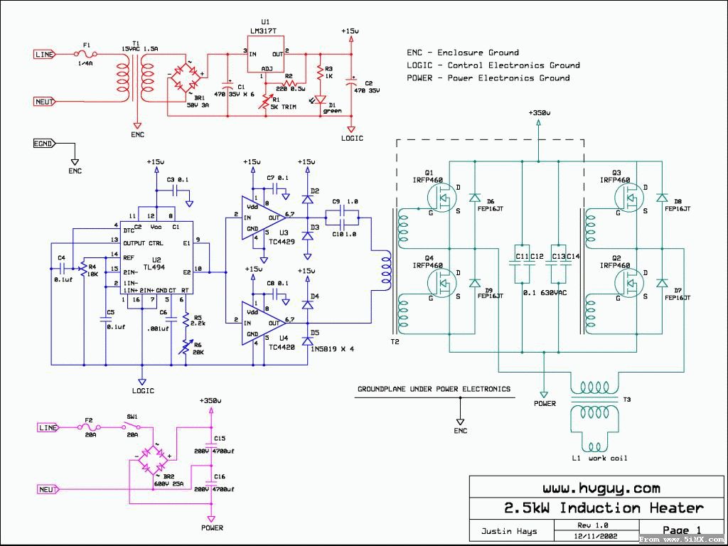
T1 ,T2 初级绕8圈 次级两组也是各8圈
IC1。。。IC4 图上型号TC4420,可能使用中发热厉害,可换为TC4421s。

Modus Operandi: Low voltage power supply, colored red in the schematic: 120Vrms is applied to the primary winding of transformer T1, and is stepped down to approximately 12Vrms with 1.5A of continuous current handling capability. The raw AC output of T1 is then rectified by bridge rectifier BR1, and filtered by capacitor C1. C1 is 6 individual 470uF 35WVDC capacitors in parallel for a final value of around 3000uF. The raw DC from C1 is then applied to regulator IC1, whose output provides precise voltage regulation for the control circuitry. The output voltage of U1 is adjustable from ~ 1.5V to 18V by potentiometer R1. Control electronics, colored blue in the schematic: A 494 type controller IC is the heart of the control electronics. This integrated circuit has several useful features, namely built-in UVLO (Under Voltage Lock Out) and duty cycle control which greatly simplifies circuit design. For this circuit, the TL494 is set up as a simple oscillator that puts out a square wave, variable in frequency from 5kHz to 120kHz, with pulse width variable in duty cycle from 10% to 90%. Clean power from the logic supply is applied to pins 11,12, and 8, and if the voltage is greater than ~7.0V the chip will power up. The output frequency is adjustable with potentiometer R6, and the output duty cycle is adjustable with R4. Capacitors C3, 4, and 5 are for local decoupling and smoothing. All components associated with U2 must be physically located within a couple of inches of the IC. The square wave output of U2 is applied to the inputs of gate drive IC's U3 and U4, which provide buffering and current drive capability. U3 is an inverting type, when it's input is HIGH its output is LO. U4 is a noninverting type, when its input is HI its output is HI. These two IC's drive the primary of isolation transformer T2 through DC blocking capacitors C9 and C10, which are necessary to prevent current spikes arising from the magnetization of T3's core. The primary side voltage is magnetically coupled to each of four secondary windings, which drive a specific power MOSFET in the power electronics section. Further information on transformer T2 can be found in the last section of this webpage. Power Electronics Power Supply, colored purple: 120VAC is applied to a voltage doubler circuit consisting of bridge rectifier BR2, C15, and C16. C15 and 16 are also used as filter capacitors. The output is taken at the negative side of C16, and the positive side of C15. The Power Electronics, colored green: An H-bridge topology was chosen for its ability to handle many kilowatts of conversion power. The main power devices are Q1 - 4, and are N-channel enhancement-mode MOSFET transistors, used as high speed electronic switches in this application. The MOSFET's in the bridge switch in a diagonal fashion, with Q1 turning on at the same time as Q2. At the next switching transiion, Q1 and Q2 will switch OFF as Q3 and Q4 switch ON. To make things easier to understand, imagine that time is frozen and MOSFET Q1 and Q2 are ON. As you visualize this with the schematic, you can see that there is a current path from GND, through Q2, through the primary of T3, through Q1, and finally to positive 350VDC. Now, we will step forward in time to the next switching transition, where Q1 and 2 are OFF, while Q3 and 4 are ON. Now you can see, that a different current path is formed from GND, through Q4, through the primary coil of T3 (other direction this time!), through Q4, and finally up to +350VDC. Now all you must do is realize that 60,000 switching transitions take place every second! With every transition, current is forced into the primary of output transformer T3. As this happens, the current is coupled into T3's secondary winding, and stepped up many times its original value. T3 is a current step-up, voltage step-down transformer. There are many hundreds of amps flowing in the secondary, and because the work coil is in series with the secondary, it means that many hundreds of amps are flowing through it too. Extreme AC currents in the work coil produce a powerful AC magnetic field around it. This field couples into nearby conductors via induction (transformer action), and if the field is strong enough it will induce hundreds of amps into the conductor itself. If the conductor is not a perfect conductor (i.e. if it has resistance), heat will be generated...and the stronger the field, the more heat! So to wrap it up, induction heaters heat inductively. Performance: So far I have been very pleased with the performance. The waveforms all look good, there are no signs of instability, and wow will it get things hot quick. It will raise a 3" length of 5/16" diameter drill bit from 60F (cold water) to 1500F in 7 seconds at 550 watts. The waveform in the above picture is the primary coil, notice the ringing from resonance in the output transformer. The lower two pictures show the 5/16" bit in the work coil, which is 6 turns of #8 stranded. It cherries after a little while but stays mechanically solid.
[ 本帖最后由 osliu 于 2007-3-22 15:30 编辑 ] |  /1
/1 